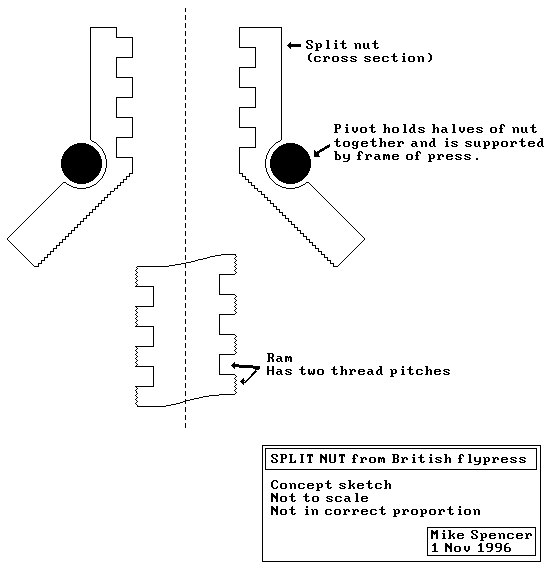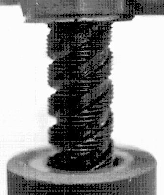
When the weight of the ram is supported by the nut, the nut is in the position shown in the sketch. The coarse threads are engaged and the ram advances very quickly for each turn of the flywheel.

When the the ram contacts the workpiece and begins to exert an upward force on the nut, the halves of the nut pivot, disengaging the coarse threads and engaging the fine threads. Then the ram's advance-per-turn decreases but the mechanical advantage increases and it's possible to apply an enormous force on the work piece by grabbing the spinning flywheel and putting your weight into running it up tight.

If you're paying close attention, you'll see that the nut as drawn won't work as described unless the supporting pivots can move further apart when the halves piviot upward. I don't remember (from 20 minutes looking at one in 1980) precisely how the geometry worked. As I said in the post, very clever design and machining.
Further info, clarification or corrections welcome.