
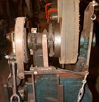
 The brake band is made from thin springy steel salvaged from an old
fashioned bedspring and run through sheet metal rolls to give it
curvature. It's lined with a strip cut from an old (rubberized?)
fabric flatbelt glued in with contact cement.
The brake band is made from thin springy steel salvaged from an old
fashioned bedspring and run through sheet metal rolls to give it
curvature. It's lined with a strip cut from an old (rubberized?)
fabric flatbelt glued in with contact cement.
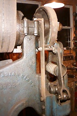
The end seen here pivots on a simple hinge which is in turn supported by a 1/4" flat bar held in place by a bearing cap nut and a ram guide bolt.
 On the other side of the hammer , the end of the brake band is
attached to the brake lever with a shoulder bolt. Just to the right
is another shoulder bolt on which the brake lever pivots. The inboard
end of the pivot bolt is fixed in a horizontal piece of 1"
sq. thinwall tube (the shiny bit behind the lever, with litle notches
in it. It's salvaged commercial shelving stock.) That piece of tube
is supported by a 1/4"x1" bar held by the bearing cap nut and another
(poorly visible, vertical, below and to the left of the pivot bolt)
held by a ram guide bolt.
On the other side of the hammer , the end of the brake band is
attached to the brake lever with a shoulder bolt. Just to the right
is another shoulder bolt on which the brake lever pivots. The inboard
end of the pivot bolt is fixed in a horizontal piece of 1"
sq. thinwall tube (the shiny bit behind the lever, with litle notches
in it. It's salvaged commercial shelving stock.) That piece of tube
is supported by a 1/4"x1" bar held by the bearing cap nut and another
(poorly visible, vertical, below and to the left of the pivot bolt)
held by a ram guide bolt.
The back end of the brake lever has an eye for the release cable and the spring. The spring is attached to an eyebolt (the tension adjuster) which is in turn held by a sort of truss. The truss is made from two pieces of 1/8"x1" and is held by the rear bearing cap nuts.
The turnbuckle is connected by a light-weight cable to the treadle. When the treadle is depressed, the brake is released. When the treadle is raised, the spring re-applies the brake. The turnbuckle adjusts brake to release at the right point in the treadle travel.