Atlas Copco compressor
|
|
| Model | KT 630A1 |
| Ser. # | 8703207 |
| Max RPM | 785 |
| Max PSI | 427 |
| Pulley | 19" dia. 4-sheave |
| Belts | Four "A" belts |
| Motor | Had 10HP, 3PH |
|
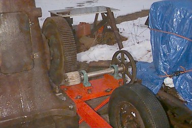
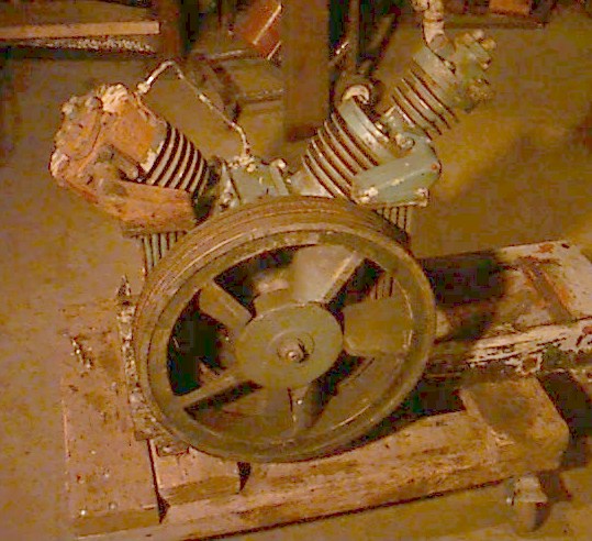 Here's the compressor, belts and motor removed. The left cylinder has
the has the air intake filter on the opposite side out of sight. I
don't know what the finned extension on top of the right cylinder is.
The pressure relief valve is in view (but a bit indistinct) on that
extension and the pressurized air outlet pipe is on the opposite side,
just a bit cut off at the top of the frame. The relief valve had
three 1/4" lock washers under the cap to shim the spring
tighter. Duh.
Here's the compressor, belts and motor removed. The left cylinder has
the has the air intake filter on the opposite side out of sight. I
don't know what the finned extension on top of the right cylinder is.
The pressure relief valve is in view (but a bit indistinct) on that
extension and the pressurized air outlet pipe is on the opposite side,
just a bit cut off at the top of the frame. The relief valve had
three 1/4" lock washers under the cap to shim the spring
tighter. Duh.
The left cylinder is connected the right one by a bundle of tubes that
pass down behind the pulley and up on the other side, apparently
acting as a radiator to cool the air.
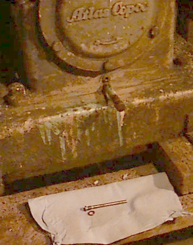 The oil drain is a capped 1/4" pipe on the side opposite the
flywheel/pulley. Just above it is a screw which, when removed, proves
to be a rather shiny rod about 3" long and 1/4" dia. that apparently
projects into the oil sump. I would say it was a magnetic particle
collector except that (a) it isn't magnetized and (b) there seems to
be evidence, in the form or a shiny spot about 1/2" from its inboard
end, that it rubs against something. What is it?
The oil drain is a capped 1/4" pipe on the side opposite the
flywheel/pulley. Just above it is a screw which, when removed, proves
to be a rather shiny rod about 3" long and 1/4" dia. that apparently
projects into the oil sump. I would say it was a magnetic particle
collector except that (a) it isn't magnetized and (b) there seems to
be evidence, in the form or a shiny spot about 1/2" from its inboard
end, that it rubs against something. What is it?
And is ordinary 5W-30 motor oil okay for this?
The small tube running from center to left cylinder head appears to
carry oil (vapor/mist?) from the crankcase to the intake manifold. It
looks as if it's stainless.
And while you're here...
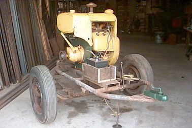
...here are some pics of hammer progress. This is the Wisconsin VE4 engine that I hope will drive it.
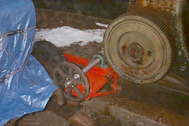
and the gear shaft, on the bench and then set temporarily in place on
its support bracket. The electric motor used to sit on a ca. 2-foot
square cast iron slab that bolted into this same space, weighs two or
three hundred pounds and was supposed to have it's own concrete pier
and anchor bolts. The blue tarp covers the Wisconsin engine. I have
yet to make the struts that hold the engine trailer in place and
tension the belts.

Created: Mon 06 Feb 2006 –– Mike Spencer