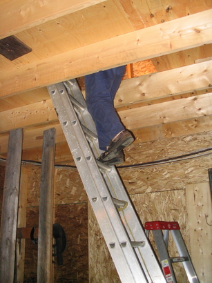
 We got real tired of climbing a ladder through a 24"x36" hatchway to
get to Peggy's weaving studio, storage space and my drafting table.
We got real tired of climbing a ladder through a 24"x36" hatchway to
get to Peggy's weaving studio, storage space and my drafting table.
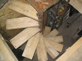
I really didn't want to lose any more space than neccessary on the main shop floor so we agreed to attempt a spiral stair.
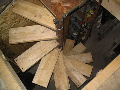
Central support pipe, separate, slip-over tread support units, 2"x10"
un-planed plank treads, ca. 130" rise, 1-1/4 turns, 12 treads per turn,
ca. 28" treads, 61" opening in the upper floor.
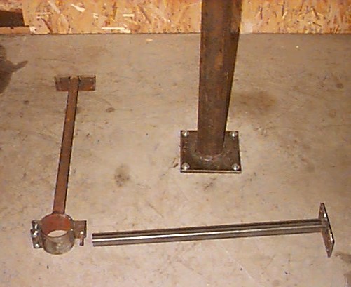
The individual treads are 4" schedule 40 pipe segments a bit over 8"
long with a support bracket welded on. The bracket material is some
kind of m/s machine housing panel from the scrap yard, slightly less
than 1/8" thick. The advantage to this approach is that each unit can
be built in a jig on the bench —— no overhead
welding, no trying to get unreachable bits alignned properly.
The bracket material was 24"x36" so I had it sheared into 24"x9" rectangles. The guys with the big break couldn't bend them up to the desired shape without distortion to I had them do this:
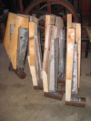 Then I welded the sheared-off piece back on to form the bracket. This
automatically comes out to make a right-angle bracket if it's put on
edges up.
Then I welded the sheared-off piece back on to form the bracket. This
automatically comes out to make a right-angle bracket if it's put on
edges up.
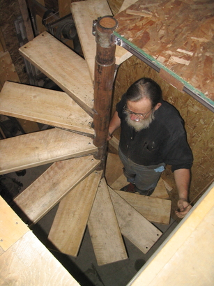
The tread units slide over a central 3-1/2" OD steel pipe that is bolted
at the bottom with concrete anchors and braced in two directions at
the top with HSS braces. The pole stands free while the treads are
dropped on. One brace then clamps to the pipe and the other is
attached with a socket and set screw. Having two parts makes it much
easier to put the brace in place from a ladder without a helper. After
everything is in place, the setscrew joint is welded.
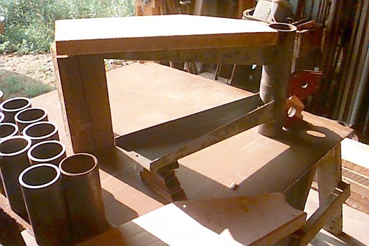
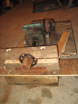 The central pole is 3-1/2" OD and 1/2" thick, some kind of extra-heavy
duty steam (?) pipe for oil drilling with stupendous pressure and
torque specs. Since I'm not a wizard welder, I wanted a real nice
joint when I welded two pieces together to get the full height
required. So I jiggered up this motor, gearbox, bearing and collet
affair to rotate the piece of pipe at ca. 10 RPM. With the other end
of the pipe in a chain-and-roller sling, I could just sit there with
the grinder on the metal while the pipe rotated and get a beautiful
bevel for a full-thickness weld on the 1/2" thick pipe.
The central pole is 3-1/2" OD and 1/2" thick, some kind of extra-heavy
duty steam (?) pipe for oil drilling with stupendous pressure and
torque specs. Since I'm not a wizard welder, I wanted a real nice
joint when I welded two pieces together to get the full height
required. So I jiggered up this motor, gearbox, bearing and collet
affair to rotate the piece of pipe at ca. 10 RPM. With the other end
of the pipe in a chain-and-roller sling, I could just sit there with
the grinder on the metal while the pipe rotated and get a beautiful
bevel for a full-thickness weld on the 1/2" thick pipe.
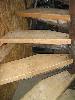 First four treads are in place. Tread #4 is anchored to the wall for
added stability. I worried that as the treads were lowered on, while
there was no support at the top of the pipe, things might get out of
balance and that 10' lever arm might lever the anchors out of the
concrete floor. So I got this wall attachment in place before treads 5
to 15 were dropped onto the free-standing pipe.
First four treads are in place. Tread #4 is anchored to the wall for
added stability. I worried that as the treads were lowered on, while
there was no support at the top of the pipe, things might get out of
balance and that 10' lever arm might lever the anchors out of the
concrete floor. So I got this wall attachment in place before treads 5
to 15 were dropped onto the free-standing pipe.
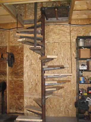 Tread, braces and landing in place. Three additional 1/8"x2" hangers
at 3, 6 and 9 o'clock. No hand rail yet. I hope to use some old
hawser but haven't figured out how to do it yet. As a temporary
safety measure, there's a vertical 2x6 (not shown) in the one place
where a misstep could be fatal.
Tread, braces and landing in place. Three additional 1/8"x2" hangers
at 3, 6 and 9 o'clock. No hand rail yet. I hope to use some old
hawser but haven't figured out how to do it yet. As a temporary
safety measure, there's a vertical 2x6 (not shown) in the one place
where a misstep could be fatal.
So there it is.
One interesting point: I didn't make any attempt to get the 4" pipe
segments perfectly aligned with each other on the 3-1/2" pipe. The 4"
pipe segments are 3-9/16" ID giving 1/16" clearance. If the tread units are
allowed to cock by that much, all the weight of the user is taken by
the pipe itself, not by the welds. The only forces on the welds that
join the segments is horizontal. That's a pretty small shear force on
the welds. So a few small welds between segments is sufficient to
keep the treads from rotating.